Following the previous article, I will continue to explain how our lost RC beacon works, especially the firmware of the receiver module. At the end of the post, a video shows how to find a lost RC model in real conditions.
Filtering noise on receiver module
Let's recap the main design of the receiver module first. We use a DRA886RX that receives the signal transmitted by the TX beacon. The output of this chip is a digital signal that can for example be used to drive a buzzer through a transistor. But doing this is a punishment for our ears because if there is no radio signal, the receiver output can randomly be 0 or 1... as a result it will output an high level noise.
The first (bad) idea to avoid this is: "hmm let's add a band-pass filter between the receiver and the buzzer calibrated on TX beacon frequency, so I will only ear the signal when we receive this frequency". Wrong. By definition, noise contains all frequencies, and if we add a perfect band-pass filter, we will hear only one frequency instead of a noise. Worst, we may not be able to distinguish the signal.
Example with 2 audio files: noise + intermittent 500Hz signal and the same with a 500 Hz band-pass filter.
The second idea is to do a FFT on the received signal. The RX beacon is designed with a microcontroler between the radio receiver module and the buzzer, so we can do some processing on the received signal. Unfortunately a precise FFT is not really possible on a 8-bit microcontroler because it would consume a lot of resources, but we can do something quite similar.
Filter details
To detect a 500 Hz square signal (this is what the TX beacon sends), we use 3 filters (FIR) running in parallel on specific frequencies. We know from its Fourier decomposition that a square signal is composed of odd-integer harmonic frequencies (of the form 2π(2k-1)f). The power of the first harmonic (n=3) is one third of the power of the fundamental frequency.
If the signal is a noise, the output of the 3 filters will have the same mean power. If the signal is the 500Hz square signal, The power of the fundamental filter will be high, the power of the harmonic filter will be lower, and the power of the last filter (1000Hz) should be very low as this frequency should not be included in the signal.
Generation of filter parameters
To generate the filter parameters, we use a python script and the pylab module. This module contains a function to generate the parameters of a simple low pass FIR from its cutoff frequency and its order. We added some code done by Matti Pastell found on the Internet to calculate the parameters of a bandpass filter.
The script fir.py generates a graph of the filters. It assumes Fe=5Khz, Ffond=500hz (blue), Fharm1=1500hz (green), Fother=850hz (red) but this can be modified in the source. The order of the filter is 32. The filter is displayed in normalized frequencies: for instance, 0.2 means "0.2 * Fe/2".
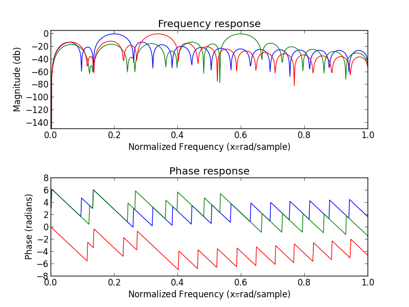
Output of fir.py
Run the script as following:
python fir.py [filename]
The script also generates the code of a C function to be copied in the AVR program. People used to program on AVR may be surprised that the device has enough power to apply 3 different filters (order = 32) on a signal sampled at 5Khz. Indeed, this is usually a work for a DSP!
The trick here is that the input signal is 0 or 1. So we can completely remove the need of multiplication to apply the FIR filter:
out(n) = a0 * in(n) + a1 * in(n-1) + ... + ak(n-k)
We store the 32 previous sampled inputs in a 32bit integer, so the code is:
       if (bitfield & (1 << 0))
               out += a0
       if (bitfield & (1 << 1))
               out += a1
       if (bitfield & (1 << 2))
               out += a2
       ...

Moreover, we use some more optimizations in the code:
- the loop is fully unrolled and all the filter parameters are directly in the code as constant to enhance speed and RAM consumption. The price is a large code in flash, but we don't care.
- the 3 filters are applied at the same time (the same "if" is used for the 3 filters)
- the calculation is done on 16 bits without overflow or saturation because we know that the filter gain never exceed 1.
We will see later in the article that the simulator shows that we have enough CPU power.
Listen and view the result
The same code can be compiled for AVR but also for a linux host. Thanks to this, we can test the effect of the filter on a real audio input. Four WAV files have been generated. They are sampled at 5Khz 16 bits, and each sample is either -32768 or 32767, simulating a 1 bit sampling (like the output of the DRA886RX):
- tone.wav: the perfect square tone at 500 hz
- tone-lownoise.wav: the tone plus some noise
- tone-highnoise.wav: the tone plus a lot of noise
- noise.wav: only noise
These files are our reference test inputs.
Depending on how the code is compiled, it will use one of these files:
make H=1 WAV=WAV_TONE
make H=1 WAV=WAV_TONE_LOWNOISE
make H=1 WAV=WAV_TONE_HIGHNOISE
make H=1 WAV=WAV_NOISE
A script output_to_audio.py is used to display the result, and save the output of each filter (fond, harm1 and other) in a separate WAV file.
In the figures below, the top graph represents the output power of each filter. In blue "fond1", in green "harm1" and in red "other". The bottom graph displays the output of the "signal detector". When the green line is 500, the signal is detected.
To generate the images, start gen-img.sh.
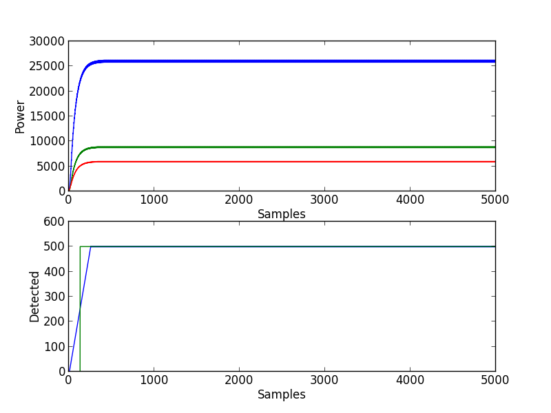
Filtering the pure tone
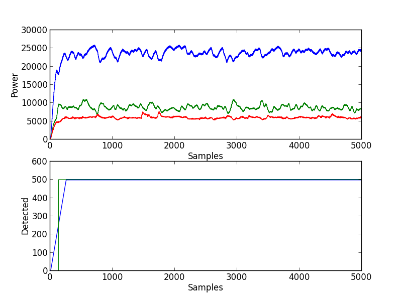
Filtering the tone with some noise
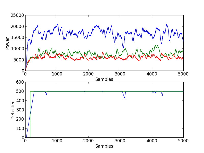
Filtering the tone wich a lot of noise
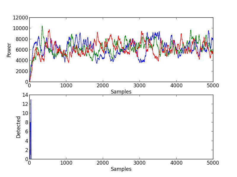
Filtering pure noise
The code that decides if the signal is detected is a bit empirical. We first filter the mean power of each filter. Then we compare their values as in the code below. When the variable cpt_filter is above a threshold, we consider that the signal is detected.
if ((pow_fond/3) > (pow_harm1/2) &&
    (pow_fond/2) > pow_other &&
    cpt_filter < MAX_CPT_FILTER)
      cpt_filter += 2;
else if (cpt_filter > 0)
      cpt_filter--;
Performance Test
We can check that the program will run correctly on an AVR by using a simulator. We simulates an ATmega128 because the ATtiny45 is not supported by simulavr:
make
simulavr -g -p 1234 -d atmega128 -F binary main.bin
Then launch gdb:
avr-gdb main.elf
(gdb) target remote 127.0.0.1:1234
Remote debugging using 127.0.0.1:1234
0x00000000 in __vectors ()
(gdb) b main
(gdb) c
Continuing.
Breakpoint 1, main () at /home/zer0/projects/zavr/projects/fir/main.c:371
371
 if ((pow_fond/3) > (pow_harm1/2) &&
Then we add a breakpoint somewhere in the loop, and do several "cont". The simulator displays the cycle value each time we go in a breakpoint.
We measure between 450 and 750 cycles for one loop iteration, so it's large enough to have Fe=5Khz! Indeed, the AVR runs at 8Mhz, so the loop frequency is 10Khz in the worst case.
The receiver in action
The receiver can work in 2 modes:
- bypass mode: in this case, the input (from the radio receiver) is copied on the output (the buzzer) by the microcontroler, there is no filtering.
- filter mode: the microcontroler will apply the filters described above on the input signal and detect the square signal sent by the TX beacon. If it is detected, a pure square signal is transmitted on the output, else the output port stays to 0.
In both modes, the LED is switched on when the signal is detected.
See the real-life video.
Thanks to serpilliere and will who helped me on this project.